【Arduino】Parallax HB-25 Motor Controlを使ってみるよ
プログラム
こちらに素晴らしい先駆者がいました。
Reefwing Robotics: Parallax HB-25 Motor Control Library for Arduino
Servo.hを使ってコントロールをしていきます。
私が使ったコードはこちら
#include <Servo.h>

#define REVERSE       1000
#define STOP          1500
#define FORWARD       2000
#define HOLD_OFF_TIME 8
#define controlPin 9

Servo servo;

void setup(){
  // HB-25 initialisation time (5ms)
  delay(5);
  pinMode(controlPin, OUTPUT);
  // Set control pin low on power up
  digitalWrite(controlPin, LOW);
  //serial confirm
  Serial.begin(9600);
}

void loop(){
  // Attach HB-25 to the control pin & set valid range
  servo.attach(controlPin, 800, 2200);
  servo.writeMicroseconds(STOP);
  Serial.println("Stop");
  delay(5000);

   // Attach HB-25 to the control pin & set valid range
  servo.attach(controlPin, 800, 2200);
  servo.writeMicroseconds(FORWARD);
  Serial.println("Forward");
  delay(5000);

  // Attach HB-25 to the control pin & set valid range
  servo.attach(controlPin, 800, 2200);
  servo.writeMicroseconds(STOP);
  Serial.println("Stop");
  delay(5000);

   // Attach HB-25 to the control pin & set valid range
  servo.attach(controlPin, 800, 2200);
  servo.writeMicroseconds(REVERSE);
  Serial.println("Reverse");
  delay(5000);

}
結果
| コマンド | M1 | M2 |
|---|---|---|
| STOP | 0 | 0 |
| FORWARD | + | - |
| REVERSE | - | + |
今回は可変電源から6V流したので、6Vが出力されています。
コマンドによって、電源の流れる向きが制御できます。
【赤外線温度センサ】MLX90614を複数個使ってみる。(Arduino)
赤外線温度センサを2つ使ってみるよ。
このMLX90614の赤外線温度センサはI2Cで温度を取得する際に、
アドレスが同じなので、このままでは複数個つなげられない。
そこで、MLX90164のアドレスを一つ書き替えたいと思います。
こちらのArudinoフォーラムを参考にすると、
以下のプログラムをArduinoに書き込み、
一つのMLX90614のみをつなげてアドレスを書き代える事ができるようです。(Connecting Infrared Thermometer MLX90614 to Wiring - Wiring参考)
※i2cmaster.hを持っていないときはgithub
Arduino Playground - I2cScanner
で入手可能
#include "i2cmaster.h"
// Pins: Standard: SDA:A4  SCL:A5
//       Mega:     SDA:D20 SCL:D21

byte MLXAddr = 0x5A<<1;           // Default address
//byte MLXAddr = 0;               // Universal address

void setup(){
 Serial.begin(9600);
 Serial.println("Setup...");

 i2c_init();                              //Initialise the i2c bus
 PORTC = (1 << PORTC4) | (1 << PORTC5);   //enable pullups

 delay(5000);                    // Wait to allow serial connection
 ReadAddr(0);                    // Read current address bytes
 ChangeAddr(0x55, 0x00);         // Change address to new value
 //ChangeAddr(0x5A, 0xBE);       // Change address to default value
 ReadAddr(0);                    // Read address bytes
 delay(5000);                    // Cycle power to MLX during this pause
 ReadTemp(0);                    // Read temperature using default address
 ReadTemp(MLXAddr);              // Read temperature using new address
}

void loop(){
   delay(1000); // wait a second
}

word ChangeAddr(byte NewAddr1, byte NewAddr2) {

 Serial.println("> Change address");

 i2c_start_wait(0 + I2C_WRITE);    //send start condition and write bit
 i2c_write(0x2E);                  //send command for device to return address
 i2c_write(0x00);                  // send low byte zero to erase
 i2c_write(0x00);                  //send high byte zero to erase
 if (i2c_write(0x6F) == 0) {
   i2c_stop();                     //Release bus, end transaction
   Serial.println("  Data erased.");
 }
 else {
   i2c_stop();                     //Release bus, end transaction
   Serial.println("  Failed to erase data");
   return -1;
 }

 Serial.print("  Writing data: ");
 Serial.print(NewAddr1, HEX);
 Serial.print(", ");
 Serial.println(NewAddr2, HEX);

 for (int a = 0; a != 256; a++) {
   i2c_start_wait(0 + I2C_WRITE);  //send start condition and write bit
   i2c_write(0x2E);                //send command for device to return address
   i2c_write(NewAddr1);            // send low byte zero to erase
   i2c_write(NewAddr2);            //send high byte zero to erase
   if (i2c_write(a) == 0) {
     i2c_stop();                   //Release bus, end transaction
     delay(100);                   // then wait 10ms
     Serial.print("Found correct CRC: 0x");
     Serial.println(a, HEX);
     return a;
   }
 }
 i2c_stop();                       //Release bus, end transaction
 Serial.println("Correct CRC not found");
 return -1;
}

void ReadAddr(byte Address) {

 Serial.println("> Read address");

 Serial.print("  MLX address: ");
 Serial.print(Address, HEX);
 Serial.print(", Data: ");

 i2c_start_wait(Address + I2C_WRITE);  //send start condition and write bit
 i2c_write(0x2E);                  //send command for device to return address
 i2c_rep_start(Address + I2C_READ);

 Serial.print(i2c_readAck(), HEX); //Read 1 byte and then send ack
 Serial.print(", ");
 Serial.print(i2c_readAck(), HEX); //Read 1 byte and then send ack
 Serial.print(", ");
 Serial.println(i2c_readNak(), HEX);
 i2c_stop();
}

float ReadTemp(byte Address) {
 int data_low = 0;
 int data_high = 0;
 int pec = 0;

 Serial.println("> Read temperature");

 Serial.print("  MLX address: ");
 Serial.print(Address, HEX);
 Serial.print(", ");

 i2c_start_wait(Address + I2C_WRITE);
 i2c_write(0x07);                  // Address of temp bytes

 // read
 i2c_rep_start(Address + I2C_READ);
 data_low = i2c_readAck();         //Read 1 byte and then send ack
 data_high = i2c_readAck();        //Read 1 byte and then send ack
 pec = i2c_readNak();
 i2c_stop();

 //This converts high and low bytes together and processes temperature, MSB is a error bit and is ignored for temps
 float Temperature = 0x0000;       // zero out the data

 // This masks off the error bit of the high byte, then moves it left 8 bits and adds the low byte.
 Temperature = (float)(((data_high & 0x007F) << 8) + data_low);
 Temperature = (Temperature * 0.02) - 273.16;

 Serial.print(Temperature);
 Serial.println(" C");
 return Temperature;
}
書き換え後に、もう一つのMLX90614をつないで、
I2CScannerで値の確認をしてみます。
以下は公式からgetしました。
I2CScanner
// --------------------------------------
// i2c_scanner
//
// Version 1
//    This program (or code that looks like it)
//    can be found in many places.
//    For example on the Arduino.cc forum.
//    The original author is not know.
// Version 2, Juni 2012, Using Arduino 1.0.1
//     Adapted to be as simple as possible by Arduino.cc user Krodal
// Version 3, Feb 26  2013
//    V3 by louarnold
// Version 4, March 3, 2013, Using Arduino 1.0.3
//    by Arduino.cc user Krodal.
//    Changes by louarnold removed.
//    Scanning addresses changed from 0...127 to 1...119,
//    according to the i2c scanner by Nick Gammon
//    http://www.gammon.com.au/forum/?id=10896
// Version 5, March 28, 2013
//    As version 4, but address scans now to 127.
//    A sensor seems to use address 120.
// Version 6, November 27, 2015.
//    Added waiting for the Leonardo serial communication.
//
//
// This sketch tests the standard 7-bit addresses
// Devices with higher bit address might not be seen properly.
//

#include <Wire.h>


void setup()
{
  Wire.begin();

  Serial.begin(9600);
  while (!Serial);             // Leonardo: wait for serial monitor
  Serial.println("\nI2C Scanner");
}


void loop()
{
  byte error, address;
  int nDevices;

  Serial.println("Scanning...");

  nDevices = 0;
  for(address = 1; address < 127; address++ )
  {
    // The i2c_scanner uses the return value of
    // the Write.endTransmisstion to see if
    // a device did acknowledge to the address.
    Wire.beginTransmission(address);
    error = Wire.endTransmission();

    if (error == 0)
    {
      Serial.print("I2C device found at address 0x");
      if (address<16)
        Serial.print("0");
      Serial.print(address,HEX);
      Serial.println("  !");

      nDevices++;
    }
    else if (error==4)
    {
      Serial.print("Unknow error at address 0x");
      if (address<16)
        Serial.print("0");
      Serial.println(address,HEX);
    }
  }
  if (nDevices == 0)
    Serial.println("No I2C devices found\n");
  else
    Serial.println("done\n");

  delay(5000);           // wait 5 seconds for next scan
}
結果

I2Cのアドレスを2つ認識しています。
では、早速2つのMLX90614から温度を取得するプログラムを作ります。
続きにプログラムを載せました。
【Arduino】放射温度センサMLX90614を使ってみる(Galileo2についても解説)
手の温度を取得するために、放射温度センサMLX90614を使ってみる。
用意するもの
手順
- 以下のサイトからライブラリをダウンロードして、Arduino > Libraries にコピーして入れる。
https://github.com/adafruit/Adafruit-MLX90614-Library
- IDEを開き、ファイル→スケッチの例から「Adafruit MLX90614 Library」を選択して、mlxtest.ioを実行する。
結果

補足
- Galileo2の利用について
Galileo2で試してみたところ、どうしてもうまくいきませんでした。
I2Cのポートをうまく認識せず、クロック数の相性があるのでしょうか。
2日取り組みましたが、よくわからないままでした。
- 1つのボードによる複数利用について
以下のサイトから、データシートを読みます。
https://learn.sparkfun.com/tutorials/mlx90614-ir-thermometer-hookup-guide
Every MLX90614 has a default I2C address of 0x5A, but that address can be re-written – one of the major features supported by the device. By reconfiguring the address of an MLX90614, you can add multiple devices (up to 127!) to the same bus to get a larger temperature map.
One last bit to note about the SMBus interface – every read or write transmission should be completed with an 8-bit CRC (CRC-8-CCITT) check using a x8+x2+x1+x0 polynomial – handy for that extra bit of data-confidence.
複数つなげる事が可能みたいですね。
【PsychoPy】Arduinoとシリアル通信をさせる。
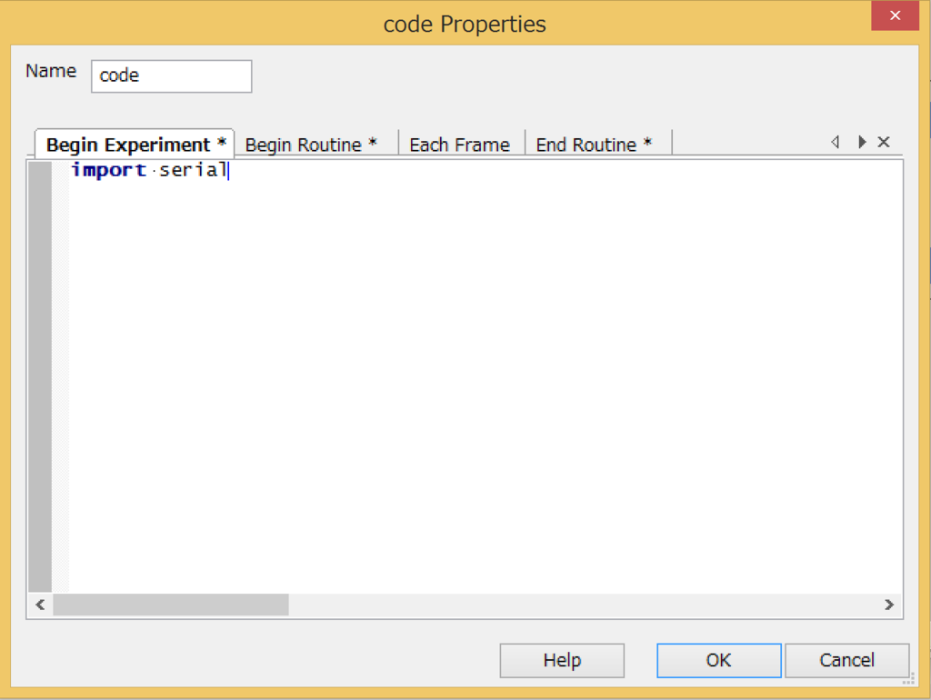
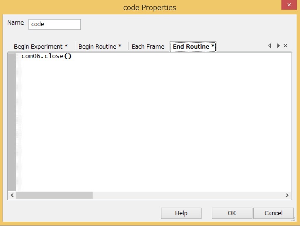
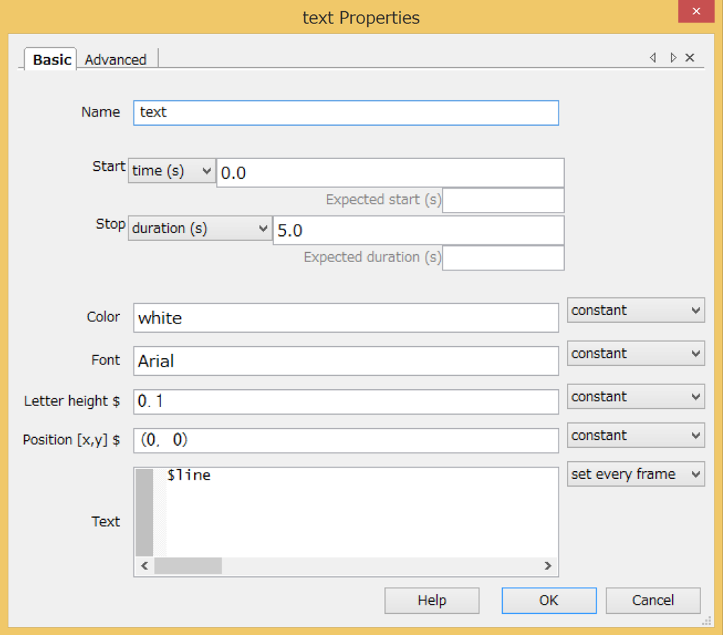
Adruino(Galileoとのシリアル通信)をBuilder modeでする。
作成したもの
- PsychoPy側から、文字列(一行)を送信
- Arduino側で受け取ったら、その値をPC側に送信
- PsychoPyのプログラムにて、表示
コード
Arduino側
#define num 30//一度に送れる文字数

void setup() {
  Serial.begin(9600);//シリアル通信開始
}

void loop() {
  char incomingByte = 0;  // 受信データ用
  char sended_value[num] = {0};
  int i = 0;

  //シリアル通信
  while(1){
    if(Serial.available() > 0){
      incomingByte = Serial.read(); // 受信データを読み込む
      if(incomingByte > 47 && incomingByte < 59 ){ //アスキーコード10進数(47~59がきたら読み込み)
        sended_value[i] = incomingByte;//配列に入れる
        Serial.print(sended_value[i]);
        i++;
      }
      if(incomingByte == '.'){Serial.print(".");}
      if(incomingByte == ';'){Serial.println(";");break;}//;が来たらwhile文終了。
    }
    else{break;}
  }
}
※ 注意
本Arduino Programはパソコン側から「0,1,2,3,4,5,6,7,8,9」「",",";"」しか受信をせず
。「;」を受信するとそこまでが1行とみなされる。
一回に受信できるコードは一行まで。
結果

【Arduino(Gallileo2)】シリアル通信 PCから送られてきた値配列に格納・表示
ほんの忘備録です。
PCから値送信→Arduino受信→配列に格納
コード
#define num 30//一度に送れる文字数

void setup() {
  Serial.begin(9600);//シリアル通信開始
}

void loop() {
  char incomingByte = 0;  // 受信データ用
  char sended_value[num] = {0};
  int i = 0;

  //シリアル通信
  while(1){
    if(Serial.available() > 0){
      incomingByte = Serial.read(); // 受信データを読み込む
      if(incomingByte > 47 && incomingByte < 59 ){ //アスキーコード10進数(47~59がきたら読み込み)
        sended_value[i] = incomingByte;//配列に入れる
        Serial.print(sended_value[i]);
        i++;
      }
      if(incomingByte == ';'){Serial.println(";");break;}//;が来たらwhile文終了。
    }
  }
}
結果
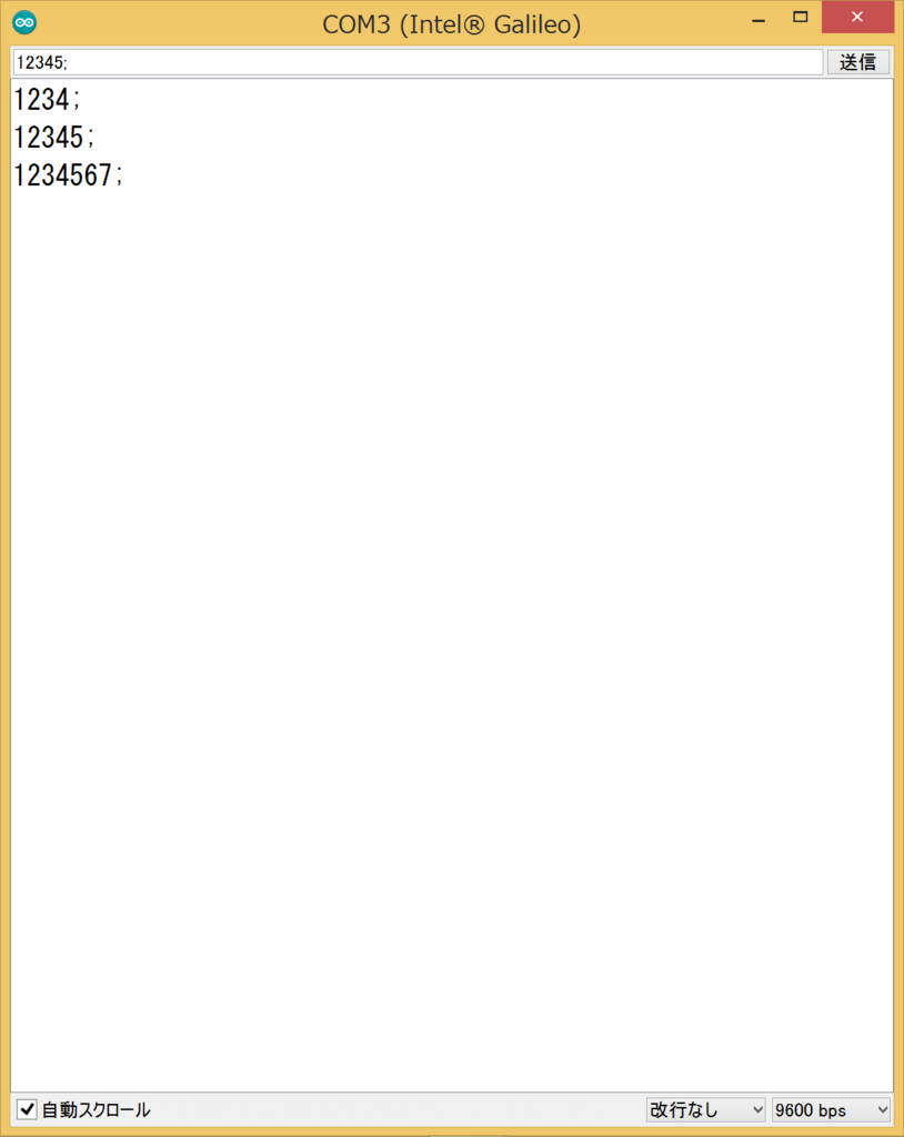
【PsychoPy】Galileo2(Arduino)とシリアル通信をしてみる。(coder編)
本日の朝、動作を確認しました。
Galileo側にコンパイル、スケッチを書き込み後、
PsychoPyのcoderモードで動作を確認しました。
以下が、Galileo側のプログラム
//------------------------------------------
//Tact switch time (P/N: 611 - PTS635SL50LFS)
//------------------------------------------
unsigned long tt, tt2, tt3;

int b_pin = 2;   // Desital pin
int ledpin = 13;
int state = 0;   // pin state
int flag = 0;

float tt4;

void setup() {
  Serial.begin(9600);
  pinMode(b_pin, INPUT);     // input setting
  pinMode(ledpin, OUTPUT);     // input setting
  digitalWrite(ledpin, LOW);   // LED pin
}

void loop() {
  float ans , temp , tv ;
  float ans2 , temp2 , tv2 ;

  state = digitalRead(b_pin);  // read data

  ans = analogRead(0) ;        // read sensor from A0 pin
  ans2 = analogRead(1) ;        // read sensor from A1 pin

  if(state == 1 && flag == 0){
    flag = 1;
    tt = millis();
    Serial.println("ON");
    digitalWrite(ledpin, HIGH);
  }
  if(state == 0 && flag == 1){
    tv = (ans*5)/1024;           // convert sensor value to voltage
    tv2 = (ans2*5)/1024;           // convert sensor value to voltage

    temp = 100 * (tv - 0.5);     // convert voltage to temperature
    temp2 = 100 * (tv2 - 0.5);     // convert voltage to temperature

    tt3 = millis();
    tt2 = tt3 -tt;
    tt4 = (float)tt2 / 1000;
    flag = 0;

    Serial.print("time:");       // output serial monitor
    Serial.print(tt4);       // output serial monitor
    Serial.print(",coldbar:");       // output serial monitor
    Serial.print(temp);       // output serial monitor
    Serial.print(",warmbar:");       // output serial monitor
    Serial.println(temp2);       // output serial monitor
    digitalWrite(ledpin, LOW);

  }

  delay(100);
 }
以下がPsychoPyのcoder側のプログラム。
import serial

com06 = serial.Serial('COM6') # open first serial port COM6
line = com06.readline()   # read a '\n' terminated line
print(line)
com06.close()
Galileo2はCOM6につないである。
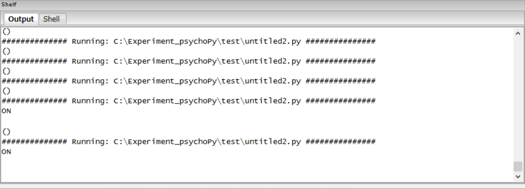
実行結果
次はviewerモードで実装してみます!


